
Digital Acoustic Modelling 2.....
Using Native Instruments “Reaktor”.
WIND INSTRUMENTS...
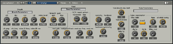
The wind panel here is actually the saxophone model. A lot can be done with this patch. A clarinet sound can be produced by using the inverted tube button and adjusting some of the ‘reed’ parameters. Various pipes and whistles can be sounded by basically over-blowing the instrument and using short tube delays. In this patch both the ‘reed’ module and the ‘pipe resonator’ have a resonance so the pipe can be sounded an octave higher by altering the ‘reed’ pitch.
In the panel above the envelope shaper module on the left is used to control the timing response to the gain changes of the whole delay loop when you press a key, which normally brings the patch up to oscillation point. This simulates blowing and fingering together in the real world. It also feeds an amount of filtered noise into the system to simulate breath noise. In the “reed” section the ‘VCA’ that actually does the gain control function I’ve called the “breath gain”. With this you can set the amount of residual gain round the loop “bias” (‘pipe’ liveness) and the amount the gain is increased when you press a keyboard key. Also associated with the ‘reed’ section is the low-pass filter that gives the ‘reed’ its inertia and resonance. The setting of this has a dramatic effect on the sound. “Reed gain” alters the amount of reed effect. It’s interactive with “breath gain”. In the middle are the controls for a ready made Reaktor module that I’ve used to limit the size of the oscillation when it starts to oscillate. This is reed elasticity. Without some control like this oscillation would just take off into severe distortion. It’s not exactly equivalent to my analogue patch but it does the job in digital and that’s what matters. The “hardness” controls adjust how radical the limiting is and will affect the sound. It’s best not to overdo it. The “symmetry” is what it says. Away from the centre of the vibration one side limits before the other.
Far right on the panel is the normal delay module representing the pipe. I’ve added an interesting control called “tube length slew limit”. It’s in some other patches as well. What it does is put a little portamento between the keyboard and its control of the pipe length. This is because in the real world players take a small amount of time to operate the valves to change the resonance of the instrument plus some time for the instrument to respond. In the models there are no valves just a direct change of tube length. Changing the length of a digital delay line instantaneously over large intervals can cause clicks too. Soften the response stops this and actually makes note changes sound more natural.
There are many controls to play with and I’ve included some presets. Press the camera icon to reveal a list any presets included.
Below are some sound clips of sounds created using this model. I can’t remember if they are all included in the preset list but they do show what can be done with such a simple model.
[SOUND EXAMPLE 28: Saxophone 1... MP3 (128kbit/sec)] [SOUND EXAMPLE 29: Saxophone 2... MP3 (128kbit/sec)]
[SOUND EXAMPLE 30: Clarinet... MP3 (128kbit/sec)] [SOUND EXAMPLE 31: Reed harmonics... MP3 (128kbit/sec)]
[SOUND EXAMPLE 32: Clarinet pipe changes ... MP3 (128kbit/sec)] [SOUND EXAMPLE 33: Pipe from the middle ages...... MP3 (128kbit/sec)]
[SOUND EXAMPLE 34: Plastic Saxophone... MP3 (128kbit/sec)] [SOUND EXAMPLE 35: High whistle pipe... MP3 (128kbit/sec)]
| Home | Previous page |
TASSMAN 4 patches and *.txf files; All zipped files here in one 48KB download.
NATIVE INSTRUMENTS REAKTOR 4 patches *.ens files; Zipped download files in groups:-
NATIVE INSTRUMENTS REAKTOR 4 patches *.ens files; Zipped download files in groups:-
Finally here’s my original basic patches again in zip form. If I clean them up a bit and add to the preset lists, I’ll post new ones on this site at some point.